Here, a chronologic report on building my first Paraset:
2008-01-28
I want to build mine as close to the original as possible. So it is imperative to use “old” components and materials. Or stuff that looks old. However, safety and reliability must be kept in mind.
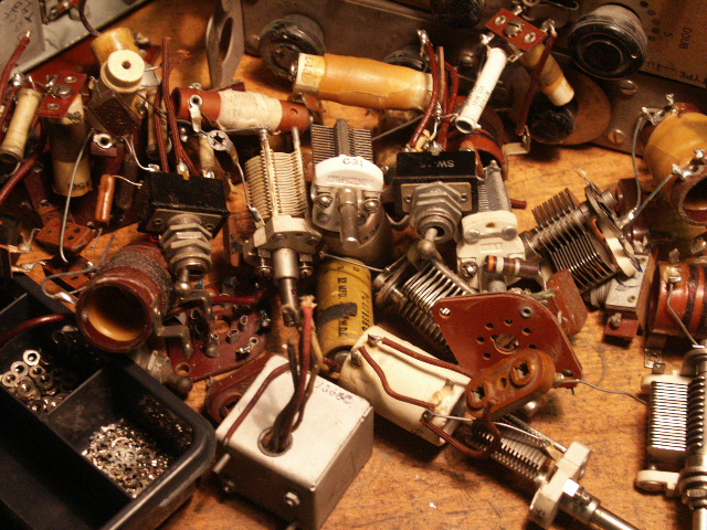
First I started to inspect various junk boxes if any useful parts could be found. Some tubes turned up and mounting struts. And two beautiful RF chokes!
Then I looked at my already cannibalised WS19’s and these delivered the tube sockets and wave band switch. Unfortunately, the sockets turned out to be too large. I will take out wiring as well, in order to wire my Paraset with old textile covered wires. Capacitors will come out also.
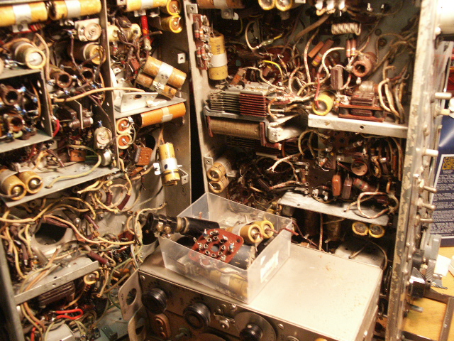
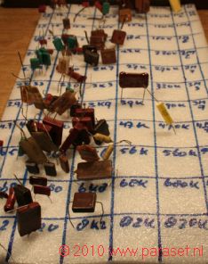
Variable capacitors (varco’s) were a problem. Luckily I could buy a number of tuning units, once used in the BC-610. Much useful material can be found in these little boxes. The best buy are units in the range between 2 – 5 Mc. These have two 100 pf type varco’s. Units higher in frequency contain 150 pf types. These can be altered by removing some of the plates. Other useful parts: knobs, receiver coils, Xtal sockets, isolating materials like tubing, nuts, bolts, washers, wax. Wax? Yes, wax! The coils in these boxes are covered with a lot of wax that can be liquefied with a hair dryer or electric paint stripper. The wax can be used for waxing one’s home made coils. That’s recycling. Or just the Dutch way….
And then you’ll end up with this…

Yummie! ….. juicy details…
2008-02-19
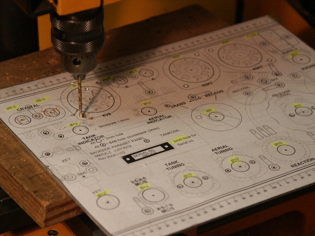
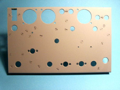
After cutting a sheet of 1,5 mm aluminium to the desired dimensions the 1:1 drawing is glued to the sheet. Then the punching and drilling starts. Start with a small diameter like 2 mm and work up from that for most precise results.
The excellent drawings can be found on SM7UCZ’s website.
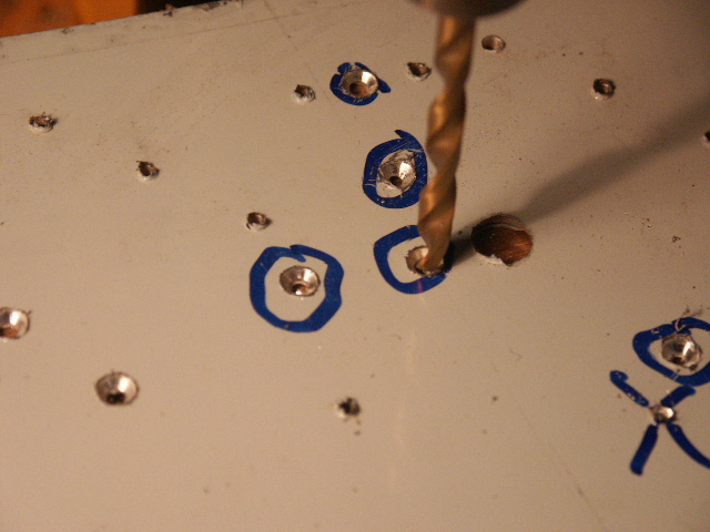
Counter sinking. As it is almost impossible to find inch-sized screws in a metric country, I decided to use 3 mm flat head bolts. The holes for these can be counter sunk with a 5.5 mm drill. Be careful not to drill to deep!
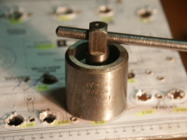
With a punch kit, bought about 30 years back (!) the big holes for the sockets are made. If you don’t have a punch like this, a jigsaw with a metal cutting blade can do the trick. I used that for cutting the rectangled power plug hole. When the large cut outs are made, it is time to bend the sides in a vise or bending tool.
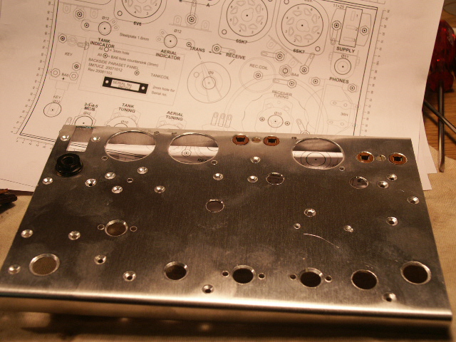
These are all the holes needed. Some smart guy told me I had better buy the holes and make some aluminium around them. Less bother, he said.
Also: the top and bottom sides are bended 90 degrees.

From the WS19 I took these mounting struts and cleaned them up. Smelly affair. But they look good, don’t they?
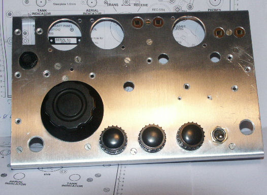
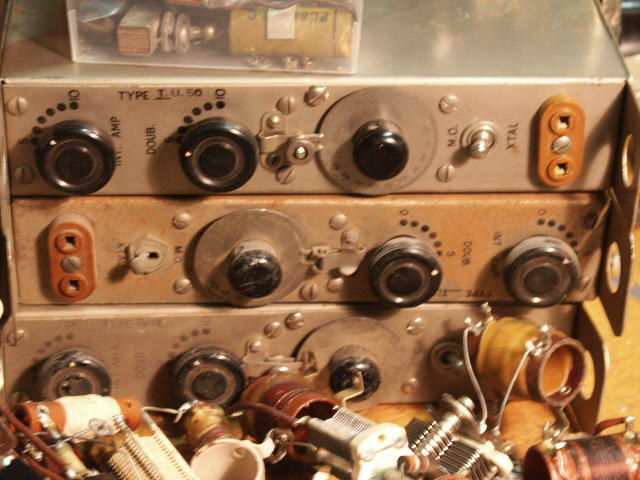
The first components mounted:
– 3 varco’s
– 2 Xtal sockets (antenna/earth and Xtal)
– headphone socket
– band switch (original WS19)
– struts
– knobs (Paraset knobs replica’s from Allan Strong G3WXI)
Looks already great, doesn’t it?
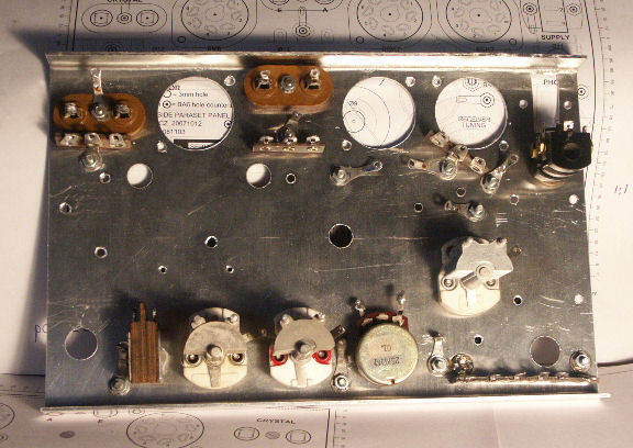
This is what the back side looks.
Still puzzling about some things, like the correct moment to put paint and text on the front panel. And how to make a slow motion dial drive with a minimum effort. How to mount the reception coil I have, in a professional manner. Still looking for a 36 H choke or something useful. The Morse key can wait…… Ah, what a wonderful hobby!
2008-03-02
I took off all major parts and spray painted the front panel. I happened to have bought a can of undercoating to do some maintenance on my car. This undercoating is a nice, flat tone of grey. You will notice that I left all the bolts in place. I want them grey as well.
For now I have to wait until a shipment from U.K. comes in. I ordered some material to make water slide transfers on my laser printer. I’ll have to wait and see if that brings a satisfying result.
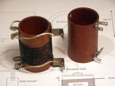
So the next thing I started working on, was the RX coil. From the TU-boxes I got nice brown cores.
I took off the wiring and the mounting struts, heated the core and wiped off the remaining wax.
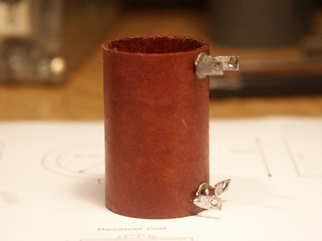
Then you get this. Further on you will see I took off the soldering lashes as well. There was no good use for them.
A Dremel power tool with a small grinding disk is very helpful for this job. You can grind away the rivets from the inside without damaging the core.
Then one holds a small core and a spool of wire in one’s hand. Winding the coil by hand is one possibility but a little help, a third hand so to speak, would be useful.
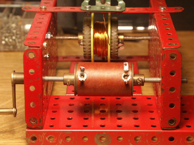
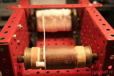
So I decided to look into my old Meccano box (Dutch imitation Meccano, that is) and make a simple coil winding machine from what I could find in there.
On one of the sites mentioned in the Link section, a book is shown, called “Building a coil winding machine“. I obtained the book and set it aside as a project for the near future. Because once you have a real coil winding machine………
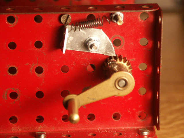
The crank and blocker. It was not a good idea to make the blocker from a piece of aluminium. When the coil was ready, the blocker was worn down and did not block anymore. Below the crank, one can see aluminium scrapings lying.
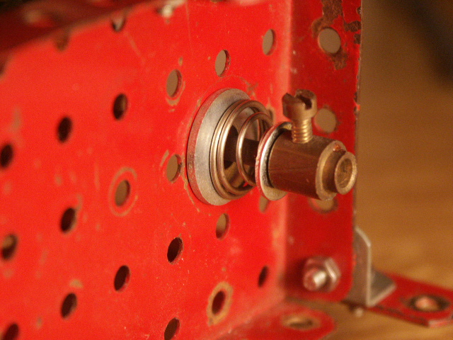
A spring provides friction for the supply reel.
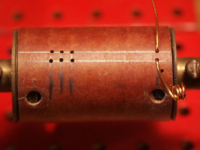
The empty core with 1 mm holes for starting and ending the windings. Later you will see a lot more holes. Being the first coil I was making, I did not plan this part very well. There is a first time for everything…

After some trial and error one ends up with this.
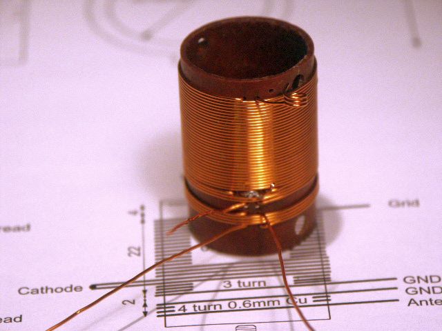
In full glory.
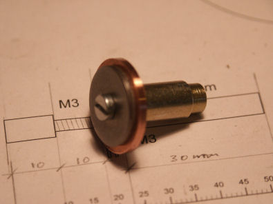
Now there is the problem of mounting the RX coil. Several ideas can be found on the web, I added this one:
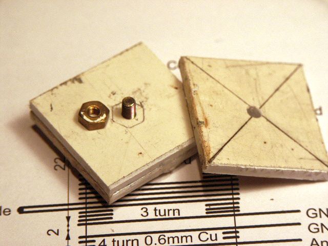
Make three square’s of PVC, a little larger than the core. Clamp them together and drill a 3 mm hole in the centre, through the three squares.
Glue two squares together and mill (with help of the Dremel and a dentists milling bit) a nut-sized hole in the upper plate. Make it tight and squeeze the brass nut in with a hot soldering iron. Caution: we don’t want the nut to sink deeper than that one square!
Yes, the PVC is a bit dirty but it will come out fine in the end – wait and see!
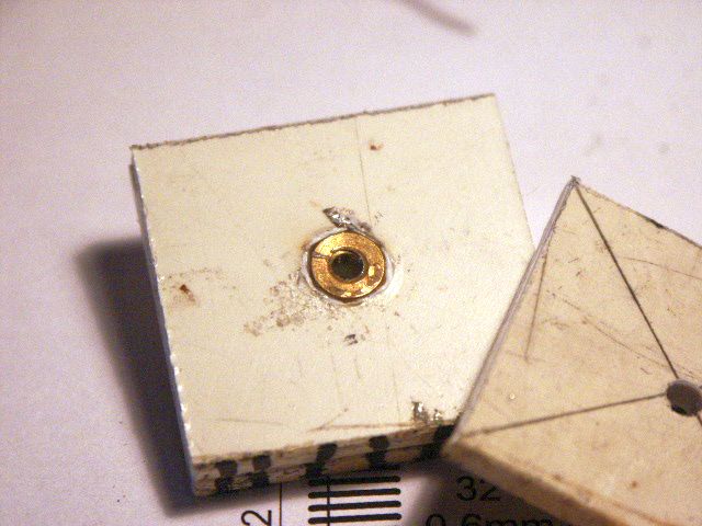
Glue on the third square so the nut comes in between two layers of PVC.

Put a long enough 3 mm bolt through the three squares and secure it with an extra nut.
Put it in a lathe and start cutting away the obsolete material.
The bottom part (close to the clamp) must be about 1 mm wider than the core outside measure. This equals one layer of PVC.
The lower part, two layers of PVC is resized to fit the inside of the core.
If you don’t have a lathe, an electric drill, a sanding disc and a file can do the trick as well.

Then you finish with this:
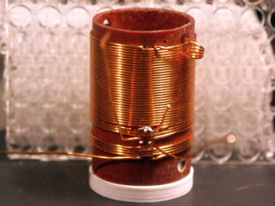
….. a coil on a pedestal!!
I am not quite happy with the coil itself. It is not quite what I had in mind. Perhaps I will make another one.
I will press the coil on the pedestal with a piece of tape between the two. I have already an idea how to join the two together in the final version.
Yes, I will paint the white thing brown!
There is a little circuit that can come in handy to determine the frequency range of a tuning circuit, made up from a coil and a capacitor. If you are interested, go here to see more (Opens in a new tab).
2009-03-17
Meanwhile, the transfer sheets came in. I decided to make the text in Excel. Not exactly a text tool, but it has very interesting possibilities to format text. Meanwhile you will have noticed that the way I build this Paraset is a rather ad-hoc kind of thing. The order of building is mostly determined by the order that the components come in. Now I have to finish the front panel first, before I can mount the electronic components.
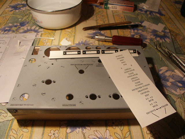
When printing, the first sheet got jammed in the printer. One sheet down the drain! TIP: set the printer for THICK paper!
After printing, things have to be prepared to apply the transfers. One needs some tools like tweezers, knives, pointy things, cloth for dipping water, q-tips, a bowl of hand warm water. The hotter the water is, the faster the transfers separate from the sheet. You don’t want that!
Did you notice the wooden side skirts I attached to the panel? Those put the front panel flat on the workspace, in spite of all the components and bolts, already in place. Later I will turn them around, when mounting components, to prevent the painted front to be scratched.
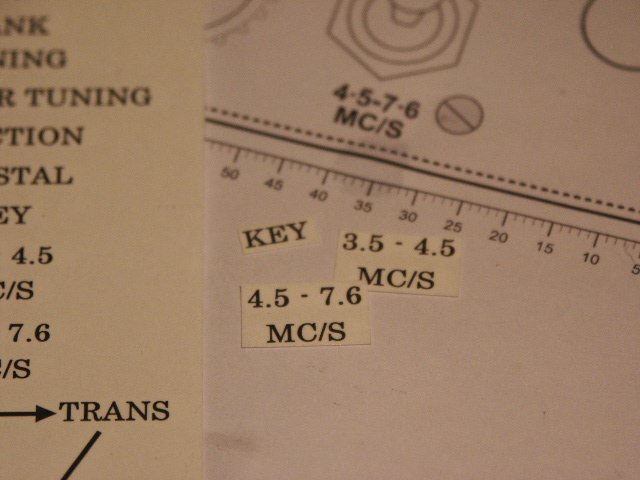
I choose the font “Century”, it is a nice “old style” font. After printing the sheet, one has to cut out the words as small as possible. The transparent material produces an unwanted shine, you will notice this later.
This transfer material comes in two types: for (colour) inkjet printers and (colour) laser printers. Alan, G3WXI, put me on the track for this supplier in the USA. Click here to go there. It has training videos that are helpful.
In the Paraset Warehouse you can find a ready printed set for your convenience.
Here all the transfers are in place. A difficult job, because you can not draw a pencil line to adjust the transfers. The pencil line will then be covered by the transfer and cannot be erased. So the eye and the hand have to do it.
Another problem arose. I used dish-washing detergent to break the water viscosity and to provide the means of placing the transfers easily. Went well. But….. water and soap stains remained.
Which brings me to the next advice: if your water tap gives water with a lot of calcium, don’t use it for the transfers! Buy a bottle of drinking water, or demineralised water, used for filling car batteries (NOT ACID!!)
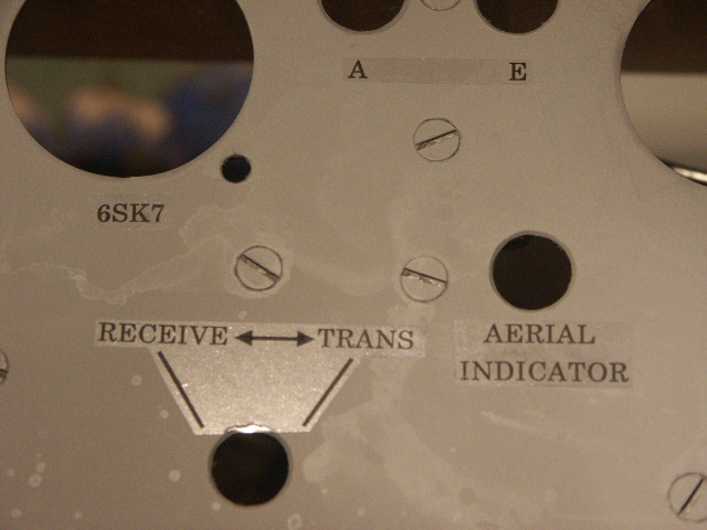
Here you see the stains in close up. Also: the shining areas of the transfers.
OK, so I decided to wash away the soap remains under the tap. Great, all the soap ran off easily. Closer inspection learned that the transfers went along, down the drain. I could start all over again!
The good news: the second time I got it better and there were no water stains. It was a lot more difficult to position the transfers in the right place, though, but the result looks great.
Next thing to do was to put the tube sockets in place. I wanted to use rivets. The only rivets I could find were those that are used for leather or denim. These rivets are a bit long. Cutting them down won’t work, because then the cap won’t fit anymore.
So I made a little tool in which I made a small cavity that could fit the base of the rivet. On top comes a washer. Than the socket, than the front plate. Of course you need six more hands to keep everything in place. A wife would come in handy, but at what price?
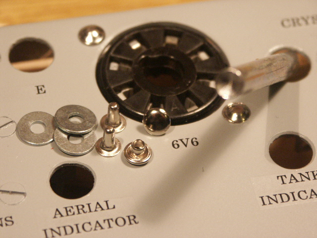
Before I worked on the panel I made some tests on some odd material. Banging the rivets with a hammer leaves you with a flat head. The rivet’s head, that is.
On this photo you will see the rivets and the tool I made to keep the rivets head, round. It is just a peace of steel where I drilled a hole in, big enough to fit the head.
With this punch, a hammer and a substantial punch the rivet is in its place, wearing a round hat.
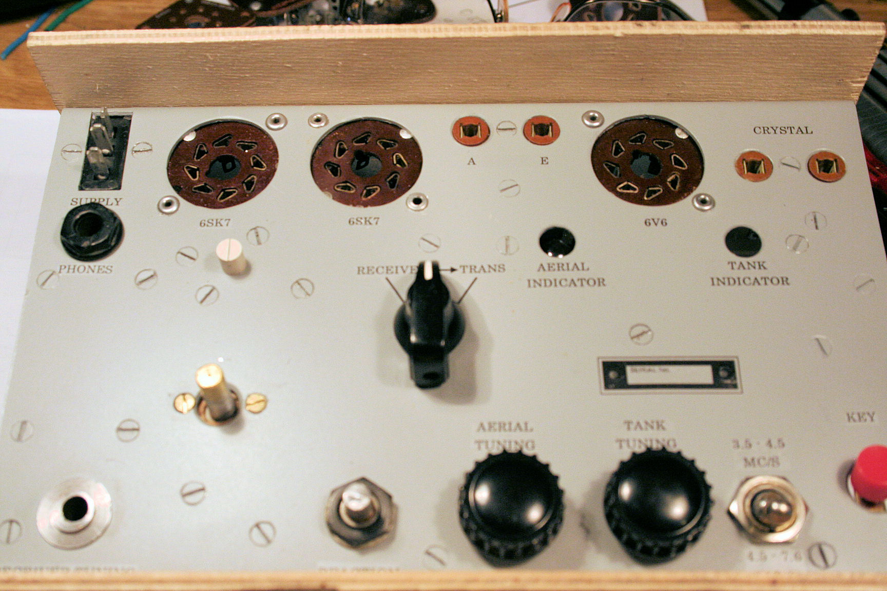
This is really looking good!
But a for more genuine look, you need to scrol down to see the other sockets / rivets I used.
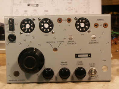
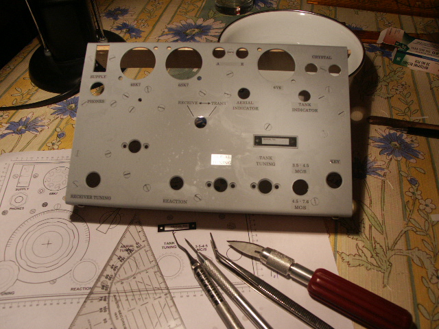
I could not resist the urge to mount the parts I already had.
The dial is not the right one, yet. But the rest looks fine to me! Click on the photo to see a bigger one.
For the time being, the serial number plate is a transfer.
Remember the white thing? I painted it. And drilled two holes in it to be able to screw it in place on the panel screw, using a pair of pointy pliers. The textile adhesive band is to secure the coil, temporarily.
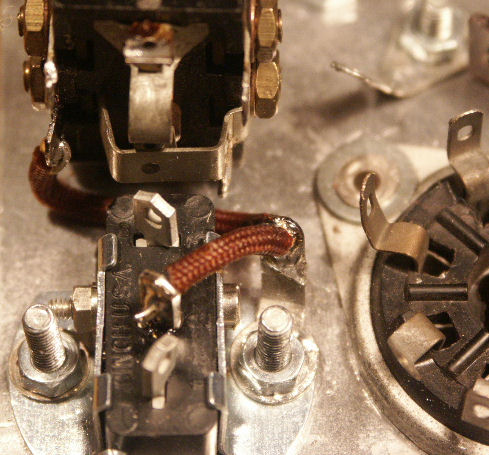
Than: a historic moment. When reading this you should pause a couple of moments, to let the impact of this moment really hit you.
The first weld!
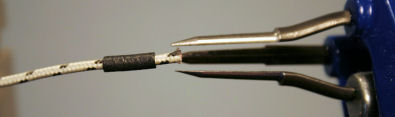
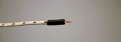
I planned to use old-but-in-good-condition WS19 textile covered wiring. Anyone who ever used that, knows that is difficult to make a nice, clean cut to clear the end of insulation.
In the old days they put small pieces of rubber tubing over the end but I don’t have those.
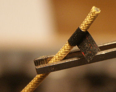
This is how I did it: I wrapped a small strip of black textile insulating tape around the wire, 6 mm or so from the end.
Update: Alan Strong told me the name of the manufacturer on the rubber sleeves and the application tool: Hellermann. I obtained the sleeves and the tool. Further down you can see the results of that.
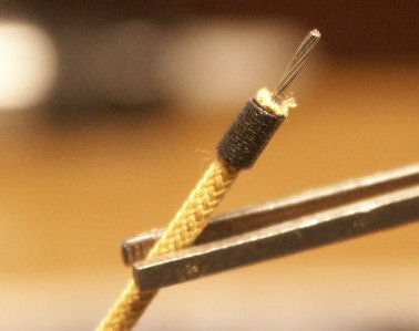
Then I used a sharp utility knife (razor blade) to cut the insulation, until I felt the metal core. Went around and ripped off the end of the insulation. Clean as a whistle! When used in the set, this looks really authentic and won’t get fuzzy!!
2009-04-14
I have found that it is paramount to finish working on the mechanical parts, first, before completing the mounting of the electronic components. So I went back to the workbench and the lathe to figure out ways to serial produce mechanical parts like the CW-key, the slomo-drive and the 16 mH RF-Choke. As I have been working on these items simultaneously, progress is slow. So you will see the progress in some parts, however they are not completed yet.
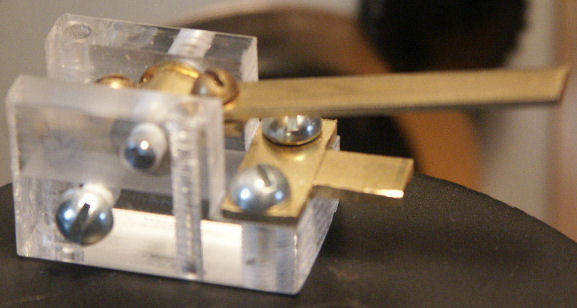
The key. A part that presents serious problems for many builders. I myself had to do a lot of searching before I had found the suppliers for the proper materials. Finally I found 20×20 mm Perspex (PMMA) for the body, brass strip for the key lever, round stock for the contact point and 20 mm round black Delrin (POM) for the knob. The only thing left to do was to make it……
One has to be very careful in reading the key drawings. Measurements are sometimes easy to misinterpret because of the given reference point.
After sawing, milling, drilling and tapping I had a crystal clear body for the key.
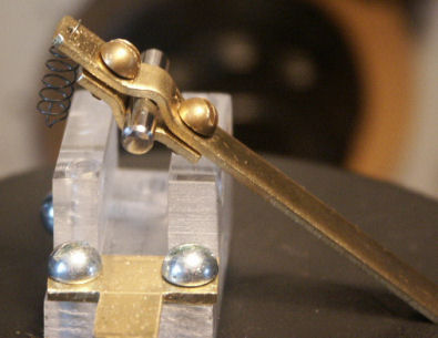
Here you see the key lever. It is bent like the original. To be able to press these curves in the arm I had to figure out a kind of tool to press in these curves. The curves turned out to be too deep for a 3mm axle, so I changed to a 4 mm axle rod. This works well.
It is not to my liking, so I will construct a better tool, to press a proper curve for a 3 mm axle. This needs some more experimenting.
More photo’s will be put here as the project continues. The contact points have to be made as well as the knob.
To be continued….
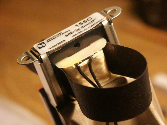
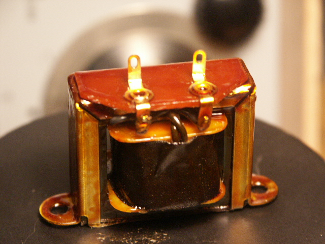
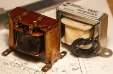
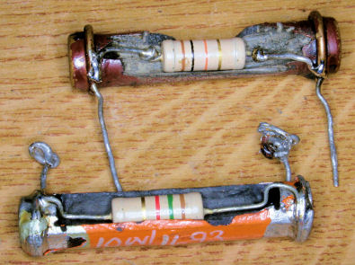
In the meantime the 60 H RF chokes came in from the USA. After being ripped off by Dutch Customs I had a number of chokes of a modern look. That had to be altered.
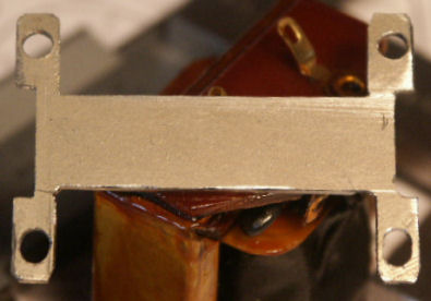
I put the sticker on the bottom, to keep the reference for future need. I wrapped a few layers of black textile insulating tape around the core to give it an “old” look.
Also the wires were bent upward, before applying the insulating tape.
But, it takes more…

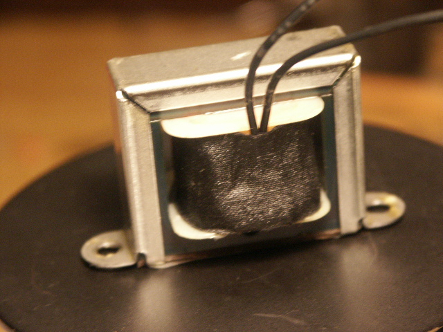
Then I painted the choke with old fashioned shellac.
How to obtain that? Easy, once you know it. I went to a shop that sells old materials for oil-painters. Not the ones that paint your house, but the art-guys.
The shop sold me a paper bag with shellac flakes and a bottle with 90 % pure alcohol. The recipe is simple: put the flakes in a bottle: one half flakes and one half alcohol. Leave it for a couple of days so the flakes can dissolve. Shake the bottle every now and then. It took two weeks and now I have a nice, thick solution.
Warning: if any alcohol is left over, don’t drink it!
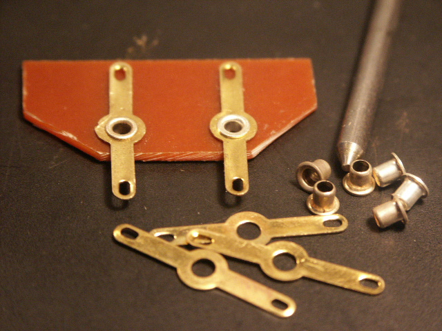
Next was to make the striking little connection board that is significant for the old choke. I made it from a piece of printed circuit board. Perhaps you will recognise the little rivets: they were used in the 1950/60 to make circuits on perforated Pertinax/Paxolin boards.
I riveted the solder eyes on the pcb. Underneath I removed the copper sheet around the rivets.
Then I tried to solder the pcb to the metal top of the choke. Bad luck, that did not work. But the heath of the soldering iron had melted the shellac and that sort of glued the pcb to the top. Beautiful!
The last thing to do is to make the base plate.
To be continued….
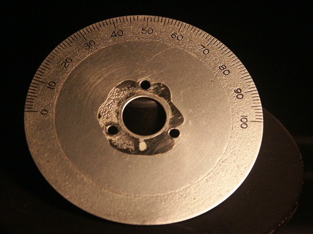
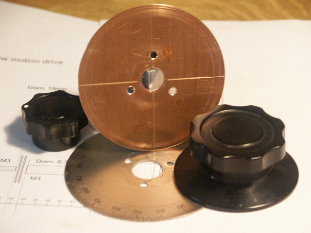
The Dial.
That is a part, hard to find. After several request on the Internet, which had poor results, Alan, G3WXI, sent me a brass dial.
It was corroded but after several hours with abrasive, polish and a dirty kitchen sink I had a nice dial.
The corrosion had left an impression like the object had been sand-blasted. Suits me fine!
I sprayed it with several layers of varnish and waited not long enough to let it dry. After mounting the knob and taking it off again, the strange stain in the centre remained. No problem, though.
I had to drill out the knob, because that was made for 6mm axle and our varco’s are 6,3 mm. I also had to remove a part of the knob at the back to make it flat. The three holes were already there, used for a scale with the wrong layout.
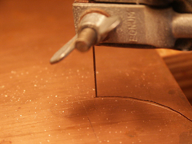
Then the drive plate had to be made. With jigsaw I took a circle out of a brass sheet. The idea was to make it perfectly round, later, on the lathe.
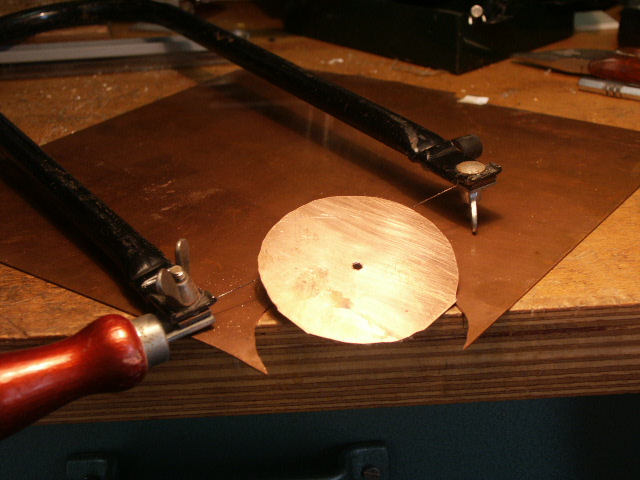
So this is the drive plate.
Watch the hole: too small to give a stable support in the lathe. I made this wider and gave it a tight fit for a M10 bolt using a reamer.
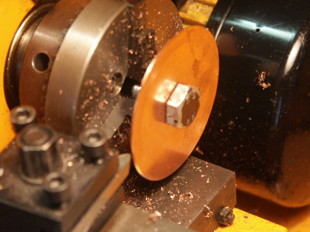
A BIG BOLT gives good stability to turn off the disk to the wanted size.
After drilling the three holes and counter- sinking them, the drive plate was ready and the dial could be assembled.
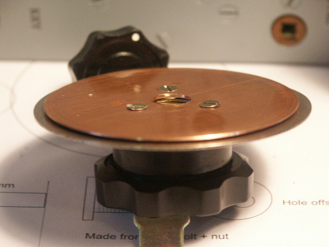
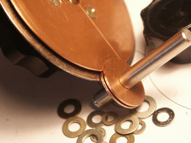
Between the two plates I put washers to obtain the needed space for the little plates that will provide the friction for the slow motion knob.
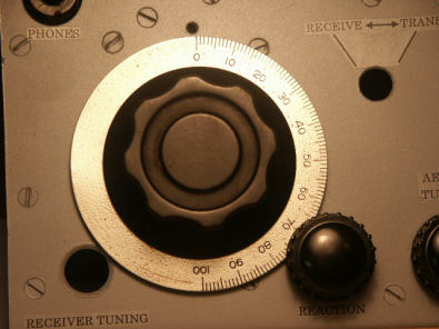
And here it is in full glory!
(Update: Later I obtained another dial, made by Muirhead. It was a complete set in original box. I measured an photographed it for your convenience. Follow this link to download a .PDF.)
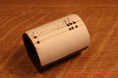
To solve the problem of finding a certain frequency on this 0 to 100 dial, Parasets were equiped with a hand calibrated chart:
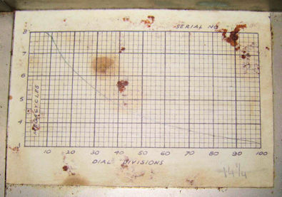
To make your own chart you can download this Excel sheet that can assist you to convert your found frequencies to above chart.
To be continued…..
06-08-2009

After a period of other things to do, I could spend some time working on the Paraset, again. Some lose ends had to be finished. The RF-Coke came first. Out of a piece of steel, left over from the TU-boxes, I cut a piece, wide enough for the base plate. On the lathe I milled out the pattern. I could have taken a (jig-) saw, but the joints in my arms give some problems, so let the machine do the work.
After a while, one ends up with this. As always, most of the material is thrown away. But it is not finished, yet. It needs a file to apply the finishing touch…..
Now, this looks more like it!
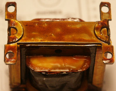
The choke mounted to the base and some shellac to make it look old.
Here you can compare the original to the Henk-choke.
Mind you, I did it the wrong way around. The proper order to make such a base is:
– drill the holes in the Paraset front;
– mark them on a wide enough piece of metal (the future base);
– draw the shape of the base on that piece, based on the hole-markings;
– make the base;
– assemble base and choke;
– apply the pcb and the tape;
– paint the assembly.
As long as the pcb is not mounted and the choke is not painted, you can clamp it in a vice to bend the choke’s mounting lashes around the base, that’s why.
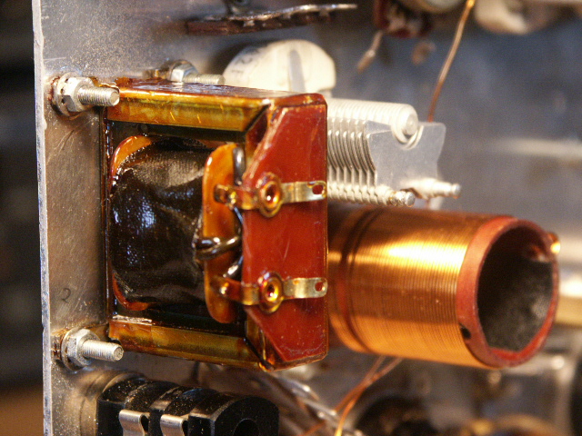
And here it is in it’s place. A good job, I think. You can enlarge this photo if you want a closer look.
07-20-2009
Next thing to do is to make the slow-motion drive for the Rx-dial. But first I will tell you about the Wave Meter Mk-IV I bought and the slo-mo-drive I found on this rig. In order not to pollute this page, I put that story on a new page, click this link to read that one.
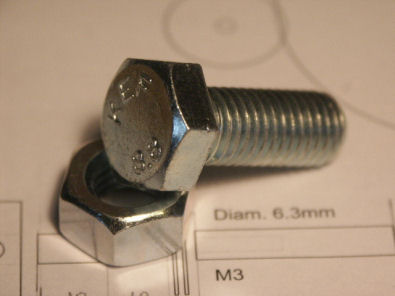
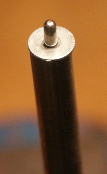
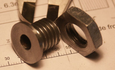
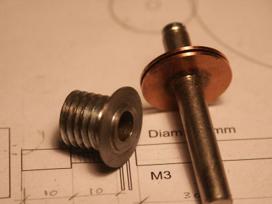
To make a slow-motion drive, one has to make an investment, first. I had to pay € 0,82 for this M12 bolt and nut.
Then take your saw and files and start working….
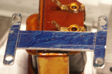
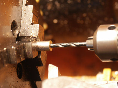
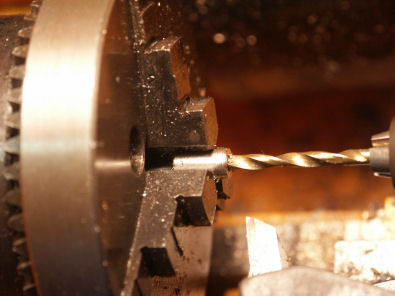
After cutting off the major part of the bolt’s head and a part of the nut, the centre hole has to be drilled. With the help of a centre-finder one draws a centre line. It helps to paint the surface that has to be scribed in a dark colour, in order to see the scribed lines better. I use a blue felt pen for that. Then, on 5 mm of the edge the 6.3 mm (1/4 inch) hole is drilled.
Then, the bearing is ready.
I can’t throw away stuff. It will be something Dutch, I don’t know. Anyway, if I cut down a potentiometer shaft, I save the left over part. So, after some 30 years, that turned out to be a good decision.
I decided to make the slo-mo shaft, slightly different than is on the drawings. This way, it is less work and the chance to be successful is somewhat bigger. You will see what I mean further on.
So, here I drill a 2,4 mm hole, about 30 mm deep, to cut 3 mm thread.
After that, I cut off 10 mm of the shaft, needed as the top part.
I enlarged the 2,4 mm hole to 3 mm to fit a 3mm bolt.

In the remaining part of the shaft, I cut 3 mm thread. The shaft is ready.
This way I do not need to turn down a piece of the shaft and cut thread in order to make thread M3. Since the shaft is made of brass, snapping off can easily happen.
Next thing is to make the brass friction plates. I cut these out of brass plate with the help of a jig saw, as I did before.
After cutting they need to be turned down to get them round and in the proper size.
In order to be able to mount them in the lathe, I used some pieces from the junk box to make a solid, temporary shaft.
After a short while on the lathe it comes out like this.
On the drawing you can see the part I altered.

This will be my slow motion drive. I use a M3 bolt (could be BA6, if you prefer that) that goes through the top part.
The only thing left is to find proper washers to make the necessary spacing.
When putting the shaft together, it is advisable to put some locking bond on the thread.
As you can see, I decided later to take some material from the top of the bearing, in order to reduce friction between the lower brass plate and the top of the bearing, in order to become a smoother action.
You can also see that the hole is off centre. That could have been 0,5 ~ 1 mm more…….. maybe next time.
It takes some effort finding washers from the right thickness to adjust the plates.
The brass I used, is 0,7 mm thick. So, between the little plates you would want 0,6 mm to properly clamp the big plate. Between the big plate and the dial you would want 0,8 mm, to keep the little plate free from the dial.
Hitting a washer with a hammer can make it a little flatter…
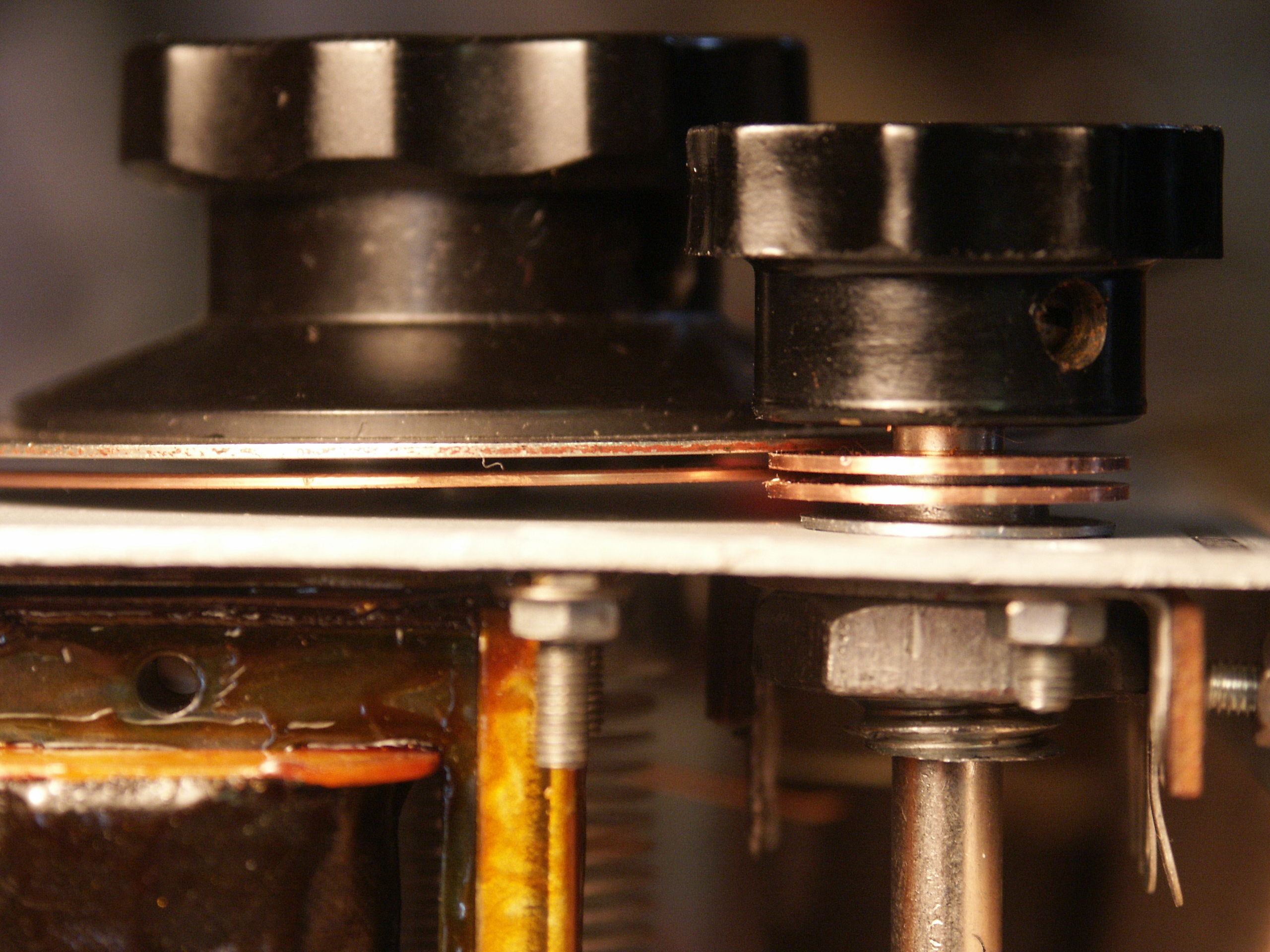
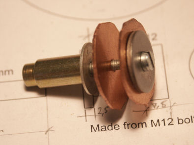
And here it is, in full glory. The nut is a bit too large, it occupies too much space and does not look good. Out of proportion. I might grind that down a bit. Click to enlarge, if you like.
It works well. Next time, I need to make the hole and shaft a little tighter, though. Building Parasets is an on going process….
Next project is to finish the key, than the mounting of the electrical components can take place. To be continued.
2009-12-29
The project came to a temporary stop. I cannot find the right components. In order to be able to experiment with the Paraset schematic, I decided to make a kind of breadboard. I described this process on a separate page for those of you who would like to see this. Follow this link….
2010-04-04
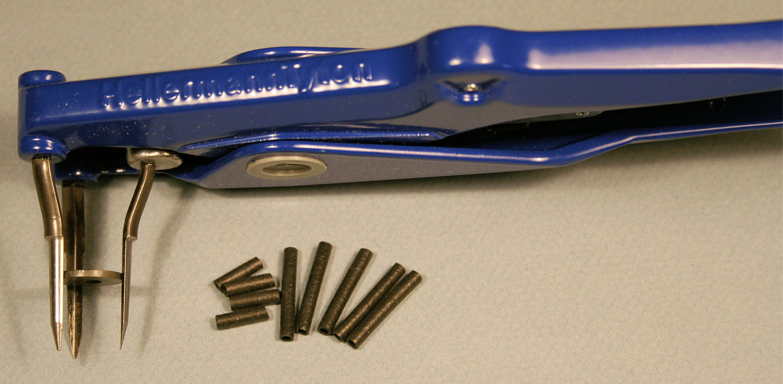
There have been some things done. I found a supplier for the Hellermann sleeves and another one for Paxolin tube and rod.
The sleeves are 20 mm long. So, in the traditon of true Dutchmen, I cut them in half, and got the double number of sleeves out of the package. And 10 mm is long enough.
I put a little washer between the prongs, so you can see them opened.
The secret lies in the pliers or application tool. It has three prongs that widen the sleeve, when pressure comes on the pliers.
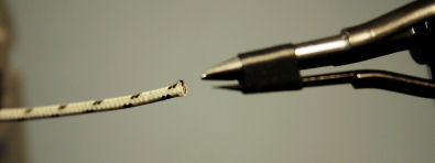
First one has to put a sleeve over the prongs. A little lubricant that comes with the sleeves, helps. This lubricant is of good influence on the cable and has good insulating qualities.
Open the prongs…..
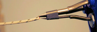
…..slide in the wire…..
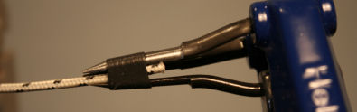
….. pull the sleeve over the wire, away from the prongs. The lubricant helps.
Cut off the insulation with the help of a sharp utility knife, and presto!
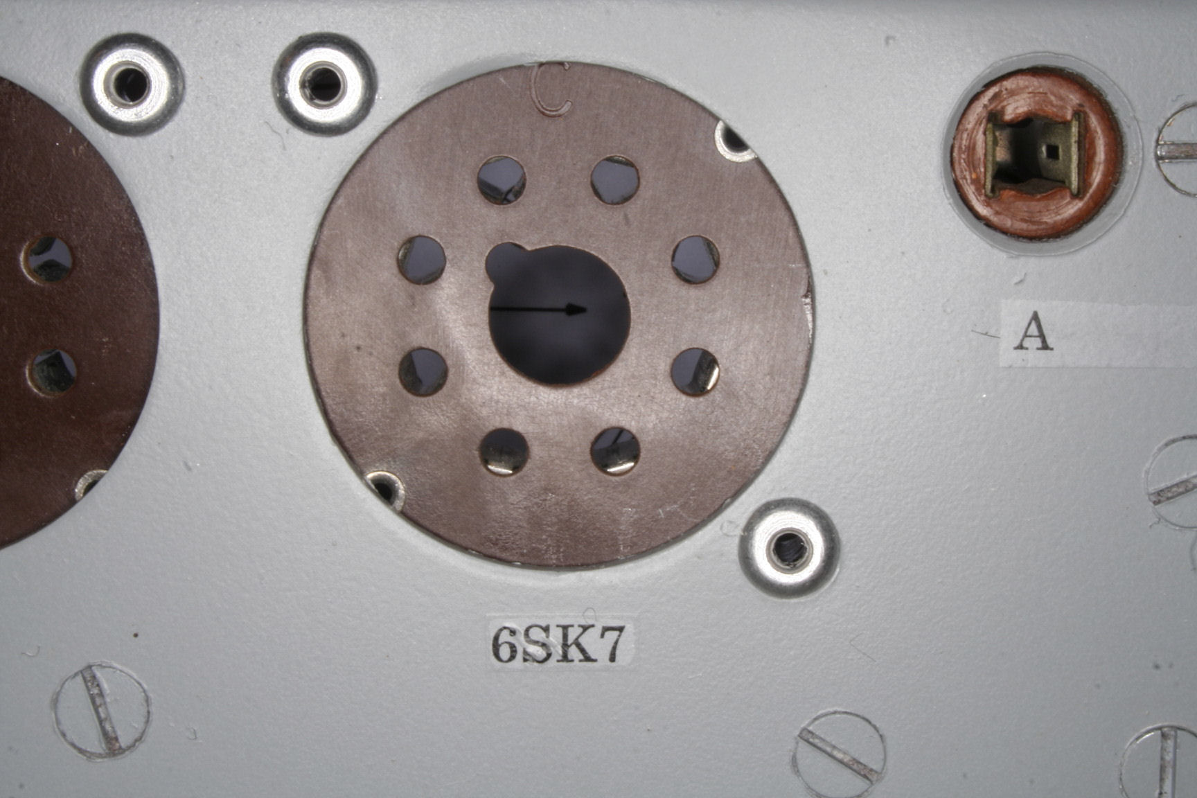
In order to make the set as close to original as I could, I decided to take out the black “modern” octal sockets and replace them by Paxolin types. I removed the too modern rivets and decided to replace those by aluminium types, the same as the ones that were used on the original sets. Thanks to Alan Oatey for the helpful discussion on the subject.
For the rivet I used ordinary pop-rivets. After applying, I used the broken off nails to knock out the nail heads, so the rivet becomes hollow, as the original were.

This is how the back side looks. When the time comes, I will make a little tool to flatten the remains of the rivet. I will use the drill stand as a press.
As you can see in this picture, it is really easy to take these sockets apart. Why would one do that? Well, …… the original ones had oval holes for the socket pins…………………………… mmmm, yes I see what you mean ……
A little tutorial on making hollow rivets you will find here.

So with the new sockets and the Hellermann sleeves, I could do some mounting of parts and wiring, again. As you can see, I removed the pedestal for the Rx-Coil. I plan to make a new one out of Paxolin tube and with cotton covered wires. You will see the details, later.
I used old components. All measured, of course, good old war time resistors. It starts to look like a Paraset, don’t you think?
That rotating switch has to go. Not old enough. And the potentiometer is J-A-P-A-N-E-S-E, for crying out loud! But I did not find an (old) English or US alternative. An old 20 K linear is very hard to find.
2010-07-09
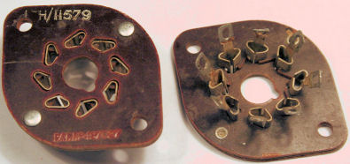
I did it again! As I found some likely-to-be original sockets, the ones with the oval holes, I replaced them again. Had to unsolder the wires and components, to drill out the rivets, but it seemed worthwhile to me.
If anyone would like to try to find these sockets, these are the numbers on them: 10H/11579, Pat.No. 487027, no brand name, unfortunately.
Mounted. See-through rivets…..
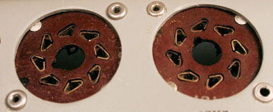
….. and a close up.
I can assure you, that these will be the last sockets to be mounted in this Paraset. When writing these words I have mounted so many components and wiring that it would be ridiculous to replace the sockets again.
Coil experiments.
Previously you saw the winding of a RX-coil. It was made from shellac covered Cu-wire. In the Paraset breadboard this coil functioned well. But it was not a coil as was used in the old Parasets, as we know from few examples. Alan Strong, G3WXI, shared an address where to find cotton covered Cu-wire: http://www.wires.co.uk/acatalog/dcc_wire.html.
With the wire I bought over there, I made another coil. In the meantime I received from Jean-Claude Buffet, F6EJU, measurement data from the original coil. I compared these to my own data and was surprised to be close to original, considering that Jean-Claude and I used different digital meters. I will put the data in a table.
First a adhesive sticker was applied to the coil former and the holes to be drilled were marked. Than drilled. The sticker could than be removed, again.
Complete coil former sets you can find here.
Remember the Mecanno box? I made some wooden dowels from my wife’s broomstick (“Henk, why is my broom suddenly flying faster?” don’t tell!) to be able to clamp the coil former. Than the windings were laid.
The reason for the dowels is that the first coil former used, was a thin impregnated cardboard type. The wall of this Paxolin tube is thicker.
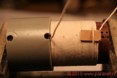
You will notice that one winding was put over a small piece of cardboard. This is for the tap that will be soldered on, later.
I used some small pieces of PVC tube with the right inside diameter to press the windings in place. I did this in the vise. Than a few layers of transparent varnish were applied to consolidate the windings and to keep moisture out of the cotton.
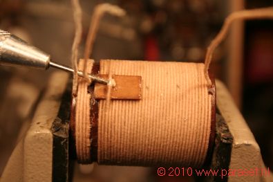
The original coil had a small piece of Paxolin under the winding to lay the soldering connection with the tap on the coil. I made this from special impregnated insulating cardboard. Looks and works the same.
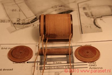
These are the parts that make the complete coil. I use an extra “cover” as you can see, to lift the coil a bit from the front panel to avoid losses. I also use a Paxolin peg or stand to keep metal (copper or steel) out of the coil.
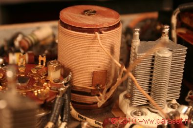
And here the coil is in it’s place. Looks pretty neat, don’t you think?
There is a little circuit that can come in handy to determine the frequency range of a tuning circuit, made up from a coil and a capacitor.
If you are interested, go here to see more.
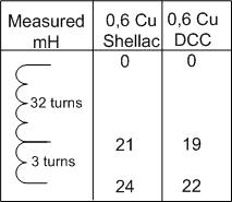
Jean-Claude F6EJU measured 22.8 mH between top and bottom of the coil, on his meter. So, my Double Cotton Covered coil gives 22 mH on MY meter. That is close. In the future I will make another coil with 0, 6 Cu Silk covered. Windings will come a little bit closer to another and I suppose the reading will come between 22 en 24.
I measured the coils in free air, on my aluminium panel and on a steel panel. This makes no difference, readings remain the same.
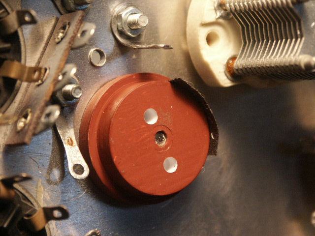
When I had mounted the Rx-coil, I took on to completing the mounting of the other components. I checked on a box full of old capacitors, but not one was 100 pf. I decided to make them myself, like some of us did before.
Of course, I used my little lathe, but you can do this also with a dentist’s drill bit in a motor tool like the Dremel or a look-a-like. It takes a little more effort, but the result is the same.
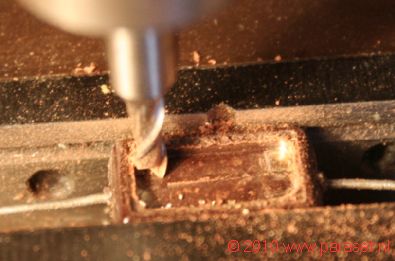
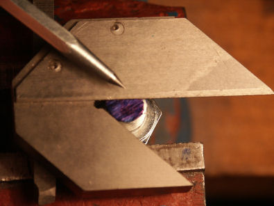
Mill a rectangled void in the back side of the capacitor.
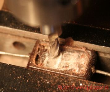
Be sure to take out all the dialectical material. In this picture you see the mill bit removing the mica. Mica is a product of Mother Nature, and not harmful.

If there is enough space, one can solder the new capacitor in its housing.
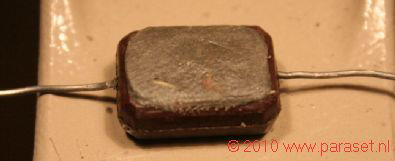
Than close it with a two-component sealing compound. That is all.
One can make this component a perfect replacement by putting the right colour code on the front, which I did not.
2010-11-22
The power resistors had to be mounted. Again, enough resistors of the required model in my junk box, but not the right value. So I decided to rebuild suitable models to the required value.
It starts with milling a cavity. I used carborundum disks on my Dremel (R) power tool to do the job. This is a messy business! Do it outside and off the wind because one does not know what material the resistors are made of. Could be asbestos! And we don’t want creepy tumours in our lungs, do we?
When cavity is large enough, the resistors of the right value can be soldered in place.
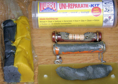
Two-component filler is used to fill the voids and to restore the original shape.
It comes in a plastic tube and one cuts off a slice brown-yellow stuff, according to the quantity one needs. Than moulding the stuff until it is one, even brown mass. Than it can be applied to the resistor cavities.
On the bottom of the photo one sees the well mixed components. It is not something a dog left behind!
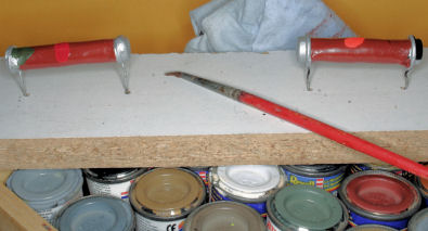
After filling and drying for a day, the resistors can be painted. A good thing I kept all these little tins of paint that I used to paint my model airplanes with.
One has to take the time for this, because paint has to dry. So it takes you 10 minutes to stir and put a drop of paint on the body and a day to wait before it is dry.
Don’t paint them too perfect! They were mass produced parts in a time when the producers were working under pressure. Less perfect is more realistic.
Now look at these beauties up close:
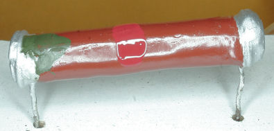

….. and here they are in place. Another problem solved.

Now I just have to put in some electrolytic capacitors and the receiver part is ready. Looking in “ye ol’ junk box” again, I think I have to perform the alteration trick once more….
2010-12-12
As the proper caps could not be found and I wanted to go on, I decided to put new caps in old tubes. That worked for some. For other caps I had no tubes with the right description, so making new labels was the obvious thing to do. Jean-Claude, F6EJU, had made several in a program called FrontDesigner, so I decided to go the same road, using his files as a base. Thanks, JC!
You can find the program FrontDesigner here: http://www.abacom-online.de/default.html.
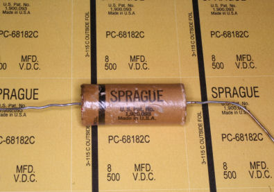
On the photo, you see an old Sprague capacitor and under it a printout of a new label. The characters are 99% identical. This label goes exactly one time around the old tube. Later I made a labels that go around, twice. When labelling a cap without cardboard tube, one has a thicker layer of paper to work with. I printed on 100 gr yellow paper, that gave the best likeness. It makes the yellow printing colour a bit darker and looking older.
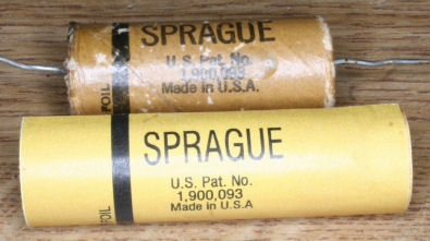
On this photo, you see the label wrapped around a 8 uF capacitor.
Now the ends have to be curled in. This is a process of learning and by the time one made the last one, one knows how to do it.
I’ll skip the experiments and tell you the best way I found so far to do this. The last cap I made, was in a 17 mm diameter cardboard pipe. The label was glued on, using a toxotropic glue. That is a contact glue that behaves like butter, when applying.
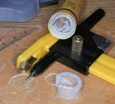
I made washers of thin isolating cardboard. On the photo, you see the cardboard pipe, the label, a piece of pipe for filling the main pipe, the cut out washer, and a circle cutting tool.
I made a metal ring of hook-up wire and covered the up-standing rim of the label, the ring and appr. 1 mm in front of the ring with contact glue.
Than the remaining label was forced around the ring.
For forming the rim one can use a rod of a small diameter, that one can roll around along the rim.
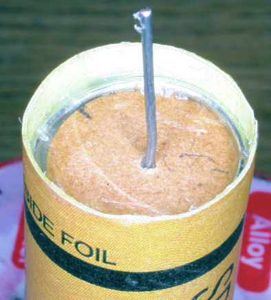
A little bit of wax is melted inside the cavity, to seal it and to disguise the cardboard washer.
Finally, a thin layer of wax is applied to the surface, to give the cap that factory-built look.
Now you know what I did with the wax, I saved at the beginning of this never ending story!
This is looking rather nice, isn’t it? In fact, the receiver part of this Paraset is finished and can be put to test. Click the photo to see a larger one.
I started to test without tubes. Applied 0 to 50 V to the B+ and raised that to 300V. No smoke.
The tubes were mounted and noise and stations were heard in the headphones. It works! But after a minute or ten, cracking noises were heard and oscillations stopped. Noises keep coming out of the headphones. I think on of the old caps, though tested before mounting, passed away.
Well, as I said before: a never ending story, indeed.
…… to be continued.