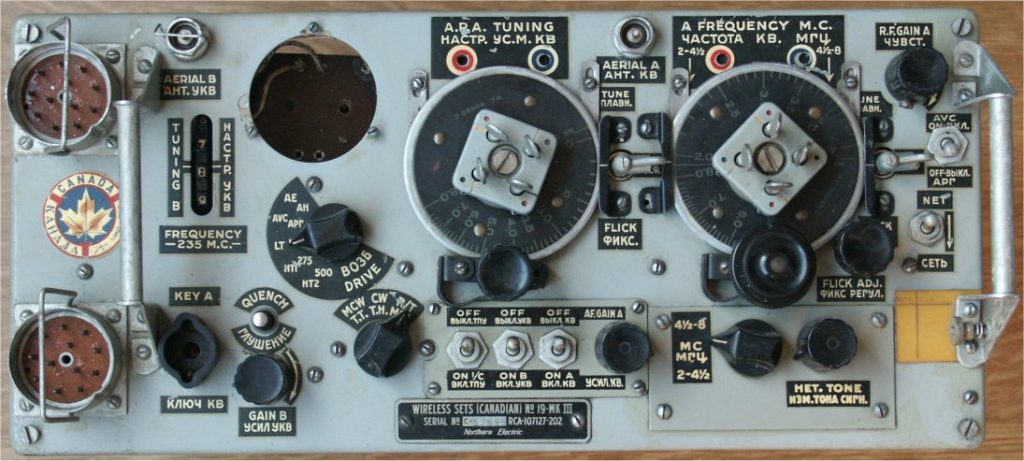
A WS19 MK-III-CANADIAN made by Northern Electric under contract RCA-107127-202. This set was last used in the Italian army before sold to Greece. Later this set came to Holland as surplus. Through various traders it came to me, every time becoming more expensive…..
This unit was in a bad shape when it was obtained. It came in a wooden cabinet, in which it was used or stored by the Italian Army. It is told that Italy sold these sets to Greece en they came from Greece as surplus to The Netherlands. So they came a long way, all the way from Northern Electric in Montreal – Canada.
In the cabinet a vehicle mounting was placed on which the set was mounted. In the cabinet I obtained, were:
– Wireless Sets (Canadian) no. 19-Mk.III,
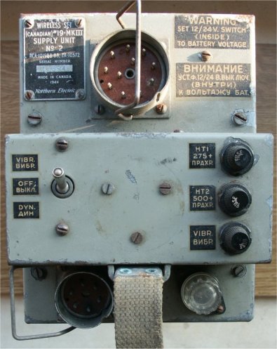
– Wireless Sets (Canadian) no. 19-Mk.III Supply Unit No. 2,
– Variometer no. 36671,
– Controlbox # and connection cable,
– Two headsets #.
Later I succeeded in obtaining:
– Case, spare parts, No. 5C,
– Case, spare valves, no. 1C,
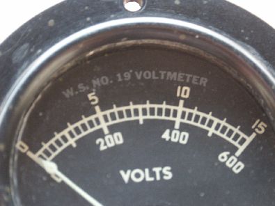
– Battery meter,
– Pocket watch.
Information on “snatch plug” Plug 5 Point No. 5 ZA 1853
Nice to see are these black & white photographs, taken in an RCA factory were mainly women were constructing these sets.
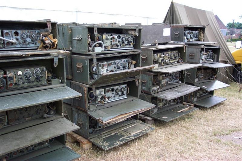
This photo I found on the web. It shows a typical surplus dump and the condition these Italian sets were in, when they were sold. Look at the enlarged photo. You will see that most of the meters are gone and the sets in their cases have been standing outside in the rain for a long time. Rust, dirt, deteriorated wood. A sad view.
Interested to see what is still in the cases: WS19, PSU, Variometer, carrier, control box, cables, headsets, satchels, signal. Of course also the spare part case, a spare valve case and a battery acid meter.
The WS19 were to be used inside the case. The lid was used as a writing surface. The antenna could be fed into the variometer by means of a special opening on top of the case.
The Transceiver part
All these sets seem to have been “demilitarized”, a euphemism for “brutally demolished”. The Volt meter was taken out and the interior got a few blows with a hammer. Strangely, the little bolts for the meter were put back in their holes.
Here you can see the painful hole. I wonder what they did with all these meters, it must have been hundreds of them.
It is not an instrument of great precision or value so why remove it?
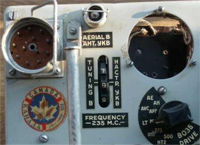
The “Canada” sticker has kept well, I am glad of that.
In the meantime I obtained an original meter, as can seen below.
The damage is not vital. Left to right:
- the cover of the B-set tuner is missing
- transformer top in the middle is broken
- the hf transformer next to the transformer had a hit, even a hole
- mounting strut on the left hand varco is broken
- right hand varco housing is dented
- the front is bended
26-06-2006: Thanks to Dirk Goos, PE1FGG, The B-set-tuner is covered, again.

The damaged parts are well visible. Temporary repair has been made by using hot glue to stabilize the broken parts.
The set works well, in spite of the demolishing.

Bottom view.
Nothing damaged, here. The bottom cover is missing. The bolts are put back in place, though.
Supply unit No. 2 Mk. III
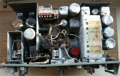
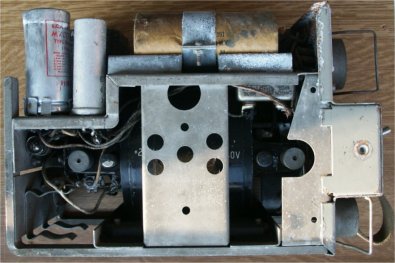
This power supply unit (PSU) is in very bad shape. It is very corroded, wiring is dried up and leaking condensers did the rest. The outside is also in a bad shape.
This unit utilizes a single rotating generator (dynamotor) for both high tension voltages: 275 and 500 Volts.
It also incorporates a vibrator driven supply system in case of single use of the receiver.
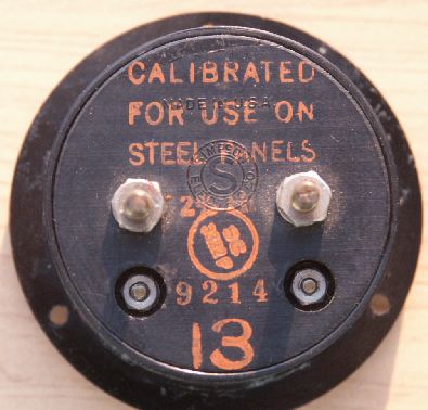
In the middle, three bolts are seen as well as an imprint of a circular shape. Originally, a Bakelite mounting ring for a pocket watch was fitted here.
These watches were supplied to the operators so the time could be noted. In those days wrist watches were probably not commonly worn. I have such a watch, only the rings are missing, on both my 19 sets.
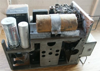
Corrosion as result of leaking capacitors is obvious.
The vibrator is located at the back (left side in the picture).
Under it, an empty spare holder is present.
A view at the engine-room.
A single rotary transformer (dynamotor) supplies both voltages: 275 and 500 Volts.
My other WS19 set uses a supply unit no 1 Mk. III. In this, two smaller dynamotors are used, for both voltages, one. It lacks the energy saving vibrator. That one is in working condition, however.
The Variometer attachment
The variometer is used to electrically adjust the fixed length vertical antenna ROD to the frequency, the set is tuned to. In the variometer is also circuit for Antenna Current measurement. Without a variometer the instrument on the front panel cannot show antenna current.
In this set up, the variometer is attached to the PSU-housing by a mounting plate.
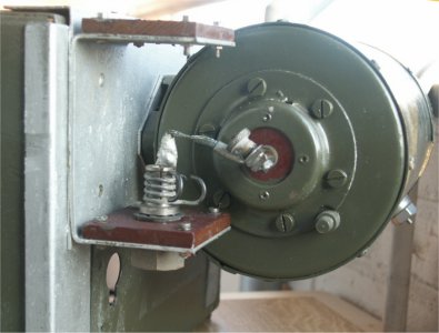
A simple, yet effective holder for an antenna rod is supplied and directly connected to the input terminal of the variometer.
In stead of the rod assembly a long wire antenna can be connected here as well, by means of the thumb screw.
At the right side of the variometer housing the output connector can be seen.
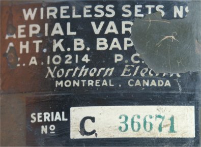
The name tag is partly gone.