On this page you can follow the development of 2 sets of three replacement Tank Coils for use in “demilitarized” GRC/3030 rigs.
These, to Dutch an Belgian Hams well known transceivers were the Dutch successors for the WS-19. They were made by Van der Heem/Philips. When the sets became obsolete they were sold to the surplus traders. But before that happened, the sets were “demilitarized”. That meant the 3 tank coils were smashed and the PA tube removed, to be sure no one could transmit with these sets ever again.
Recently, after having seen my Paraset coils, I was asked by Louis ON5LBL if I could recreate these tank coils. And after studying the subject and making a drawing, I decided to give it a go.
There is a discussion going on, whether these coils should have a adjustable core of some kind. So I will make a solution that provides a possibility to add a core afterwards.
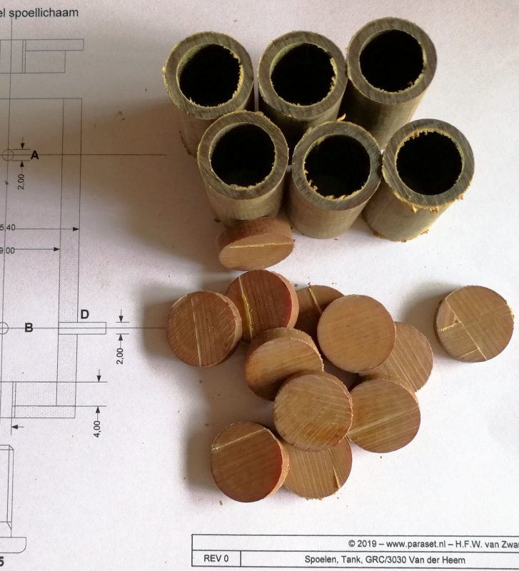
I use the same material as used in the Mk-VII Paraset, Tufnol or Paxolin, a material based on phenolic resin.
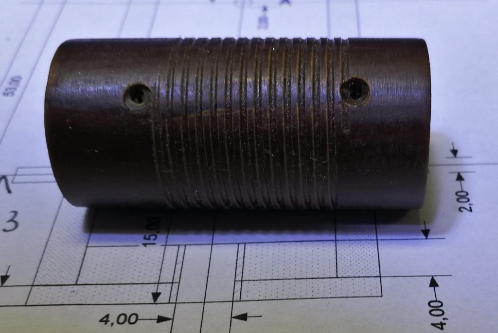
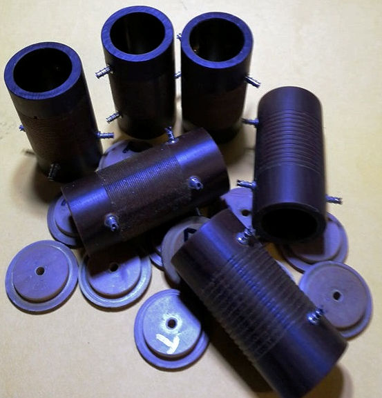
July 5, 2019. Today I made a start by cutting the raw material from stock:
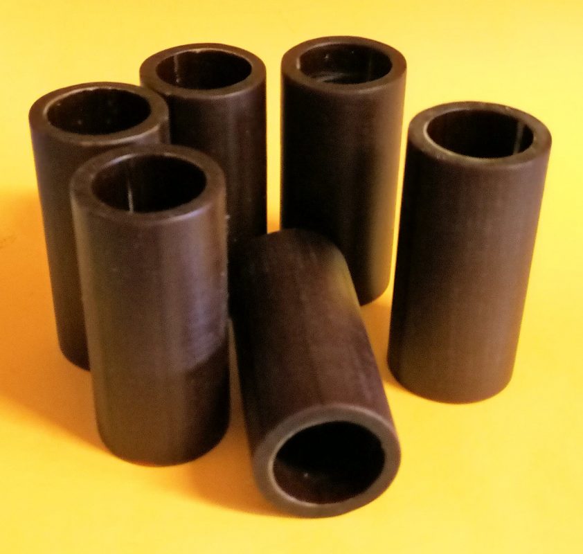
The raw tubes need to be polished. Just for the looks, I know.
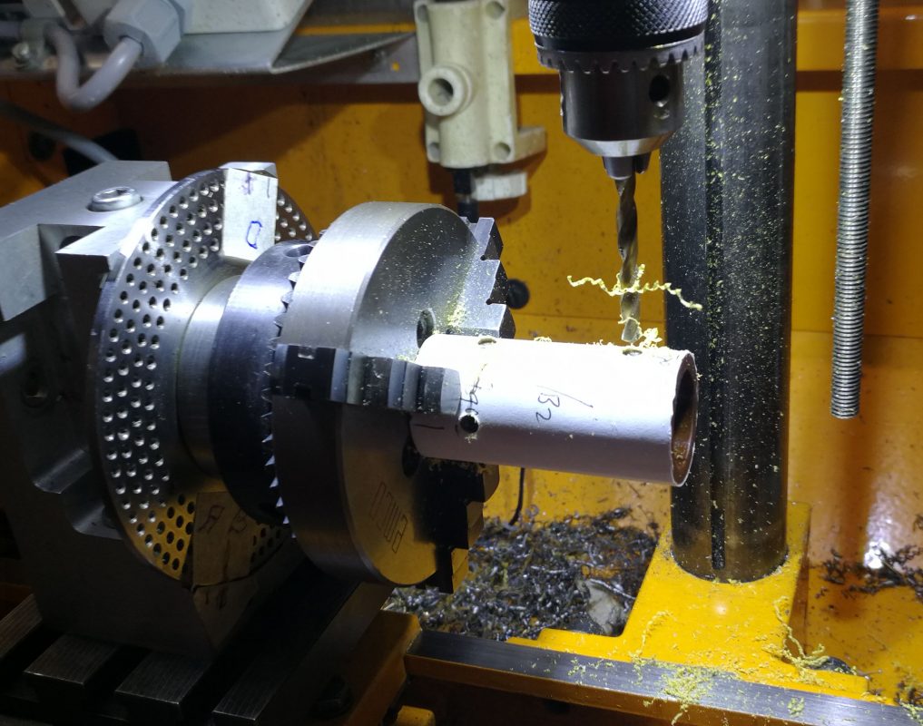
Then, after putting measures on the tubes, the drilling can start. I use a divider tool to make the holes 90 degrees apart. First a 2 mm hole is drilled, than the hole is counter sunk at 4 mm.
July 7, 2019. Worked a bit more on the GRC-3030 tank coils.
Made a small, round chisel to cut the 1 mm thread and adjusted the lathe to cut with 1 mm space.
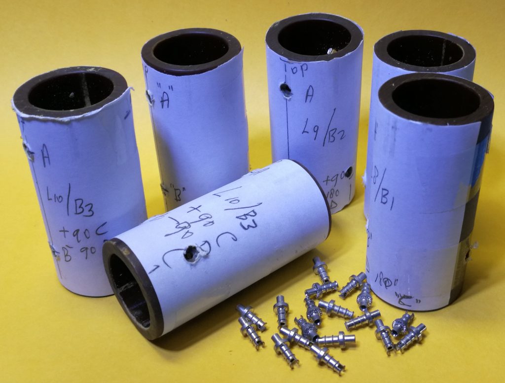
Put in the stubs after making a little tool to do so.
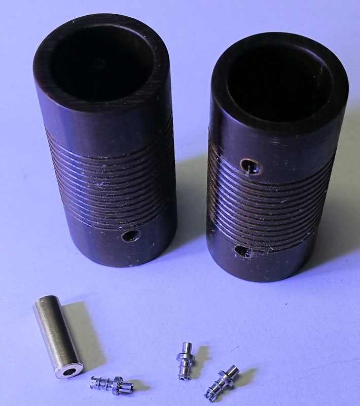
The first 2 are ready to be wound!
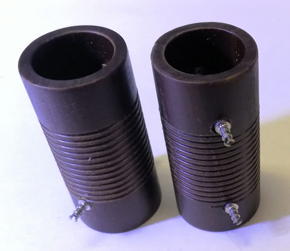
But before I start winding them, I will finish the other 4 coils.
July 20, 2019. Today I threaded the last two coils with the finest pitch: 0,6 mm, for loading them with 0,3 mm, 0,3 mm spaced. I also made the lids flat:
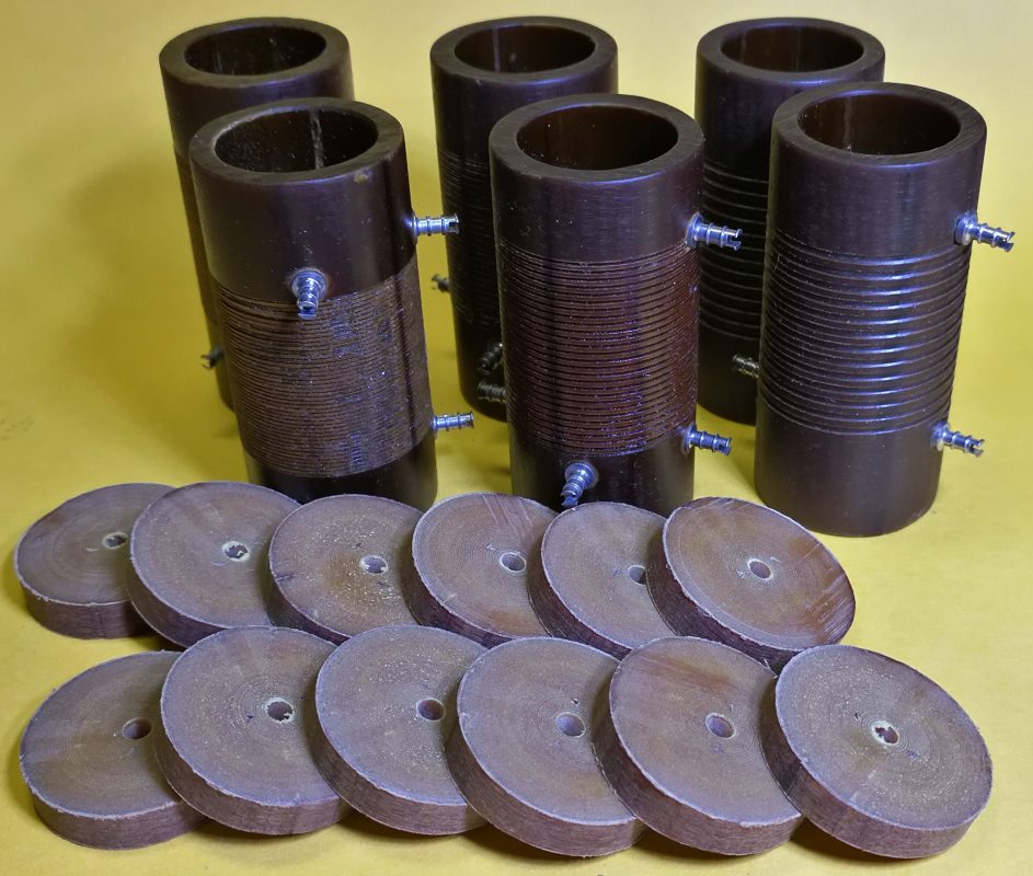
Next thing to do is remove some material from the edges to leave a rim of 2 mm.
July 23, 2019. Today I made the top and bottom covers. Next is to wind the wires on it. The coils have a thread to guide the wire. By time, in the top covers a means of adjustable core has to be made. Need to do some thinking on that.
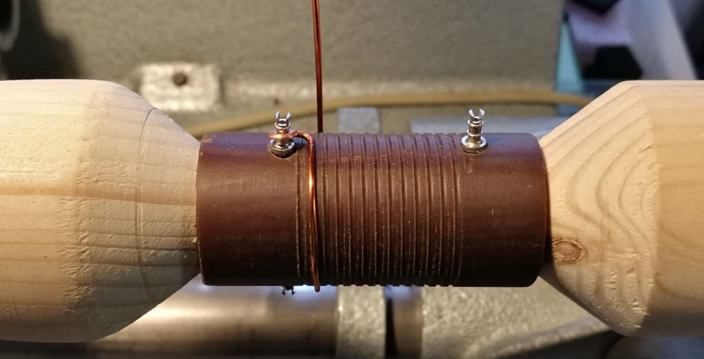
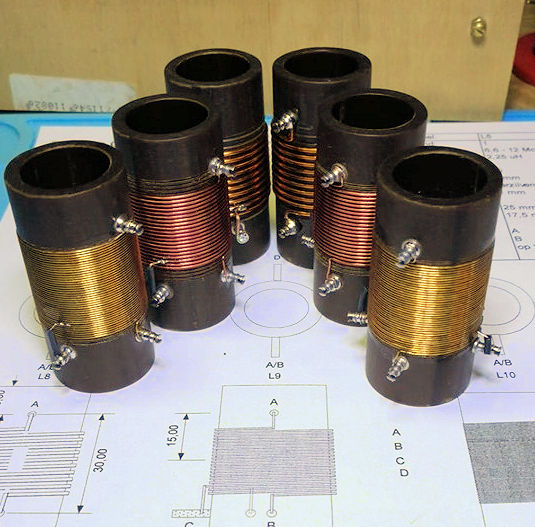
August 08, 2019. Today I put the windings on the two formers for Band 1 (L8). It needs 1 mm copper wire, spaced 1 mm apart and you have to tighten it hard to get the wire nicely on the former. Luckily I have the Aumann winding machine as a third hand. I have put a hand crank on this machine to not have to use the motor. That comes only to use when 1.000 or more windings have to be laid. With help of the crank I can wind the few turns, needed, on the former and guide the wire in it’s thread.
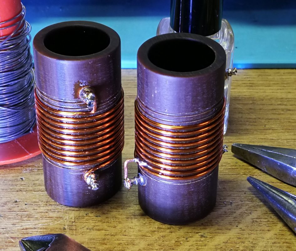
After a while – man, how time flies!! – I ended up with two nice coils. The winding starts at point A and ends on B. There is a tap on the second winding, called point C. The left coil shows points A and B, the right coil shows point C.
August 8, 2019. Yesterday I made the two coils L9. Compared to L8 are their windings double in number but the wire and spacing are half as thick.
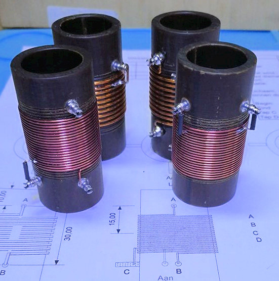
….. and today I made the two coils L10. Again, almost twice as much windings as L9 at almost half the wire diameter and spacing.
Next are the bottom lids to tap thread in and the top lids to provide with adjustable ferrite cores……
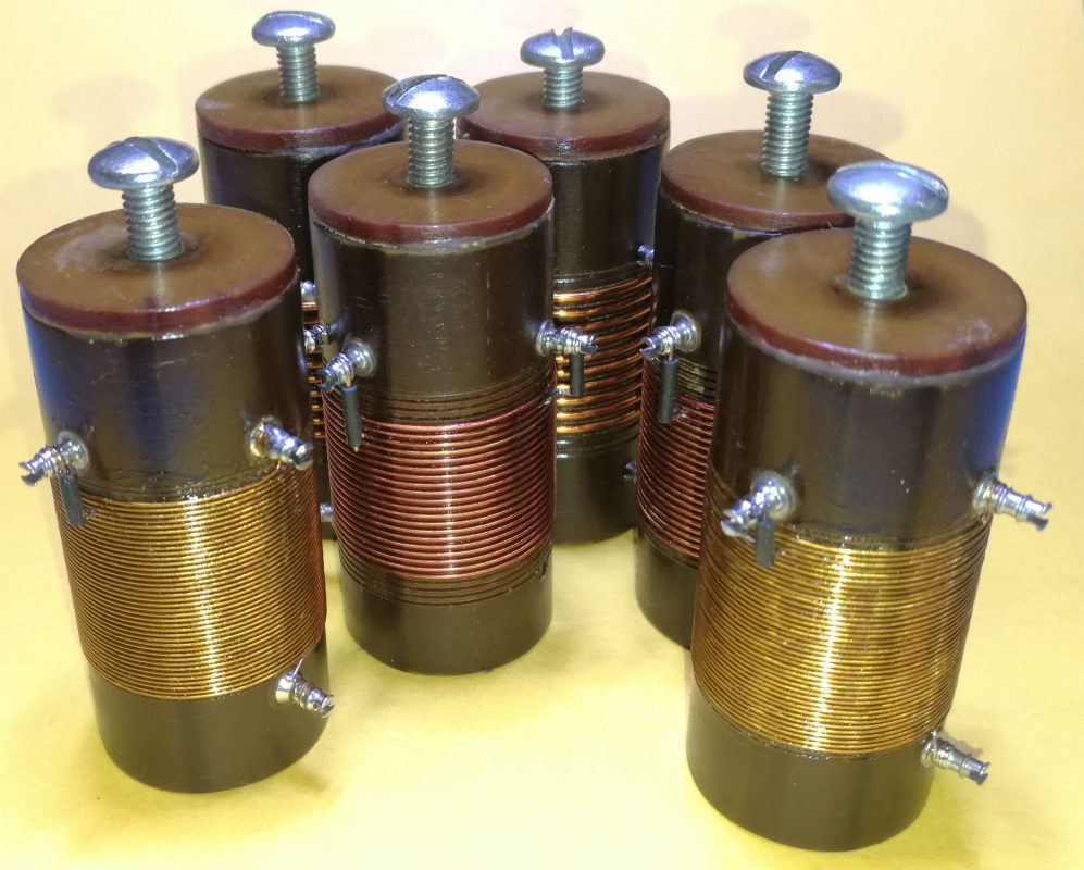
August 9, 2019. Today I tapped thread M5 in the bottom lids. And glued them in place, using epoxy glue. Next challenge: the adjustable ferrite cores. In this photo you see them standing upside-down.
August 14, 2019. I looked through my collection of MF-transformers to see if I could find cores that I could use.
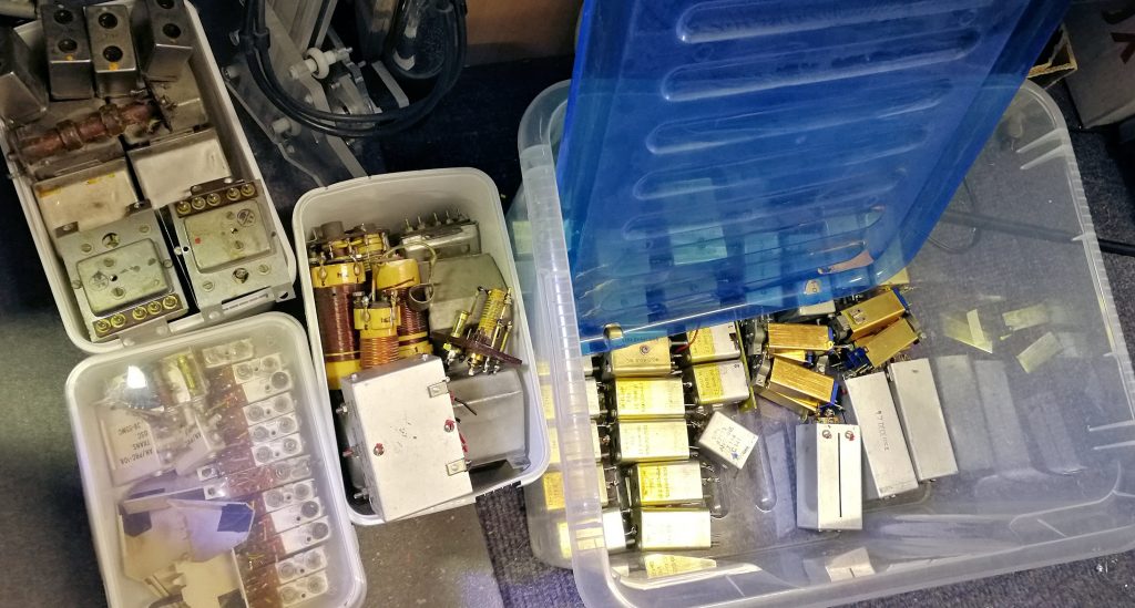
I did not. There were one or two that could be of use, but not 6. Bummer! I went through my collection of ferrite cores.
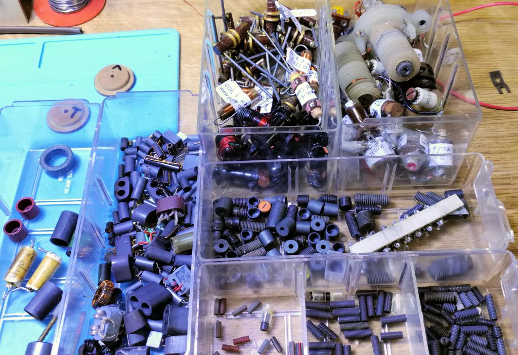
Well, I did not find 6 that had enough mass to influence the coils enough. The other problem was how to make these little cores adjustable. I did some experimenting by just shoving those little cores into the coil and measure the difference they made. That gave me an impression of the mass I needed.
Then I decided to experiment with ferrite rods, as used in transistor radios for AM antennas. Drilling a hole in that material to put a bolt in, is no option, that does not happen. I tried to cut it with a diamond disk in my Dremel powertool……
….. that worked! The next one to cut, I will do outside, this high speed cutting produces a lot of nasty dust. Shoving this lump (10 x 14 mm) into the coil gave a satisfying change in the L-value. Now how to make this adjustable if one can not drill a hole for a piece of thread? The solution came pretty quick to my mind. I decided to used a brass bolt M4 and thread the hole in the top lid.
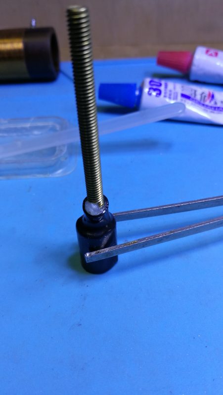
The head could be glued to the ferrite but how to keep it it in place during the curing of the epoxy glue?
A piece of shrink tubing does the trick! You need a tight fitting tube, push the ferrite in, until it is about 2 mm under the rim and apply some epoxy to the head of the ferrite. Then push the ferrite with the bold head, all the way down.
Next, shrink the tubing with the help of a heat source (hair dryer, paint stripper or rework soldering iron). Now let the epoxy cure, standing up.
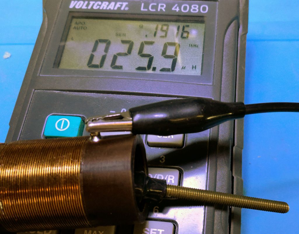
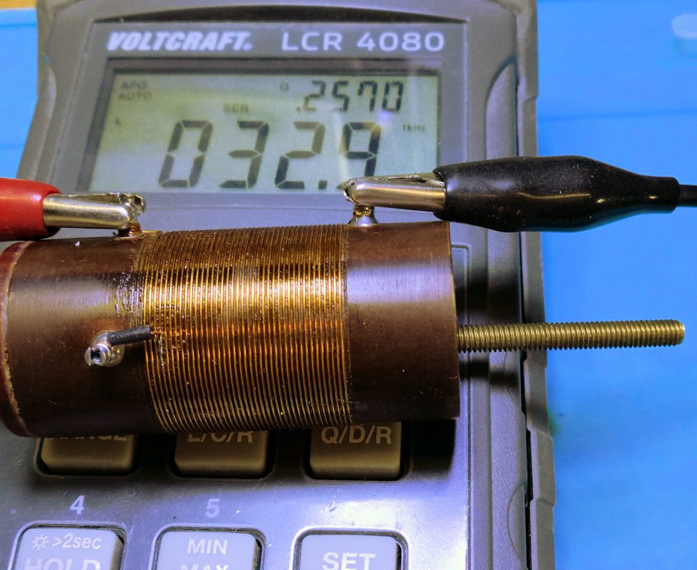
After a while one can test the effect of the core in the coil. Next two photos show the results of core out and core in the coil.
Now this prototype works, I can start making 6 cores according to the above findings.
(to be continued – watch this space!)